Pressure Hull
I used the previously-built pressure hull sections from my U-505 build in U-190.
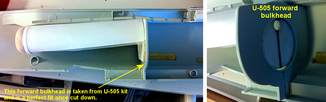
Of note is that the bow section of the pressure hull (described below) is attached to the forward bulkhead of the U-505 kit, which does not exist in the U-190 kit... but it fits perfectly.
Some of the pressure hull plans (in PDF format) are the full size of the kit (46" x 8.5") and were made originally in CorelDRAW X3.
- FULL PLANS (18-page PDF)
- Reference (PDF)
- Pressure hull sections (PDF): (Don't ask me why I started section A at the stern instead of the bow.)
Materials List — Pressure Hull
Here is the list of materials that I used to construct the inner pressure hull:
- Acrylic Pipe :
Hollow acrylic pipe
2¼" O.D.
1m length
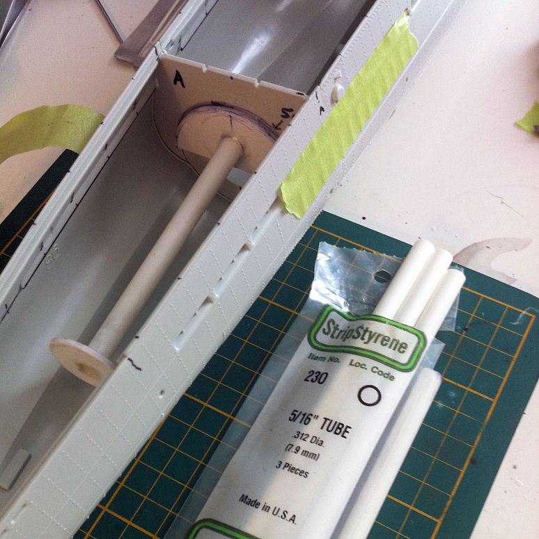
- Spine:
Evergreen Scale Models StripStyrene #230 hollow tube
5/16" (.312" dia.)
- Ribs:
Sheet styrene 0.080"
- Shelves:
Strip styrene 0.080" x 0.125"
- Skin:
Sheet styrene 0.010"
(large sheets)
- Spray Adhesive:
High-strength, permanent spray adhesive
Pressure Hull : Stern section
Download instructions HERE for making Stern section (fits both Type IXC/40 and IXC)
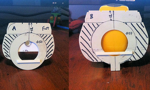
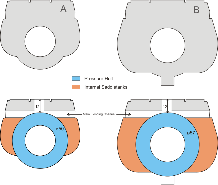
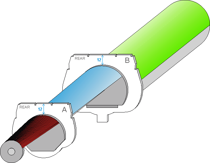
Pressure Hull : A–B section
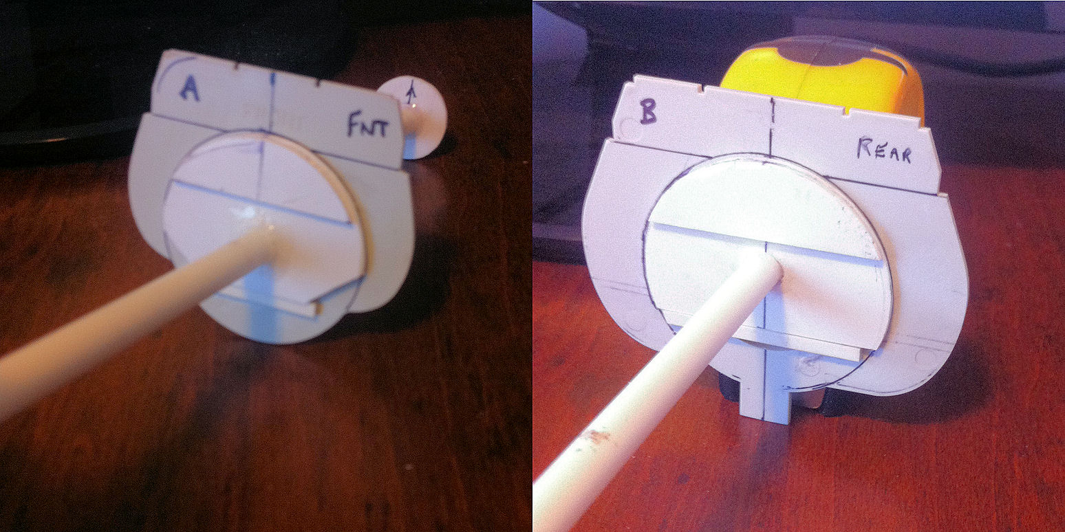
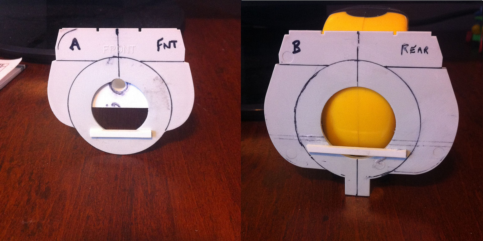
Download instructions HERE for making A-B section (fits both Type IXC/40 and IXC)
Pressure Hull : B–C section
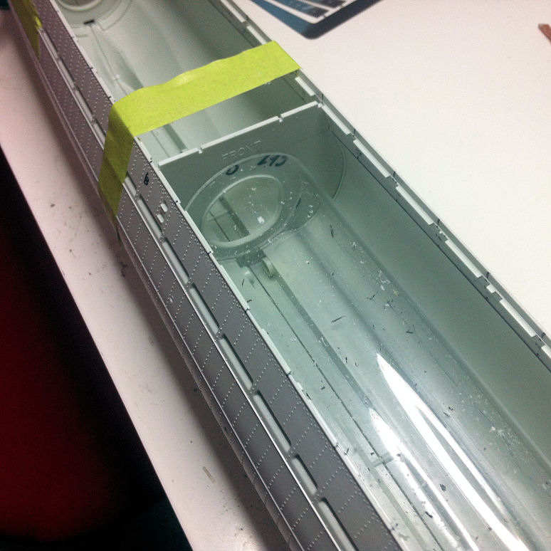
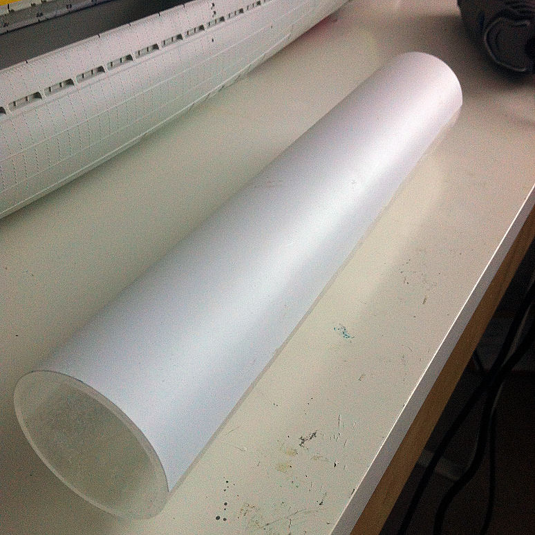
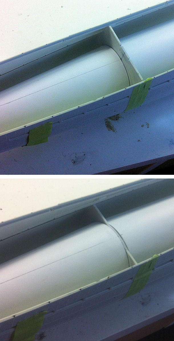
The B–C pressure hull section was by far the easiest thing to make. The diameter is a constant ø57mm for a length of ~309mm.
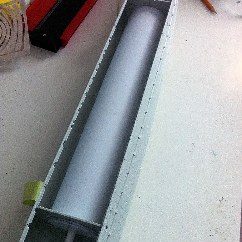
I obtained a length of 2¼" O.D. (57mm) acrylic pipe from my local plastic store, and cut it to length using a radial arm saw. I carefully trimmed the acrylic tube so it fit snugly between bulkheads B and C.
To apply the 0.010" styrene skin:
- Spray the 0.010" styrene sheet with high-strength adhesive spray.
- Align acrylic tube to edge of styrene sheet.
- Roll acrylic pipe onto styrene, back 'n forth like a rolling pin. The styrene bonds to the acrylic tube with no wrinkles.
- Wrap the skinned tube with masking tape, leave it to set.
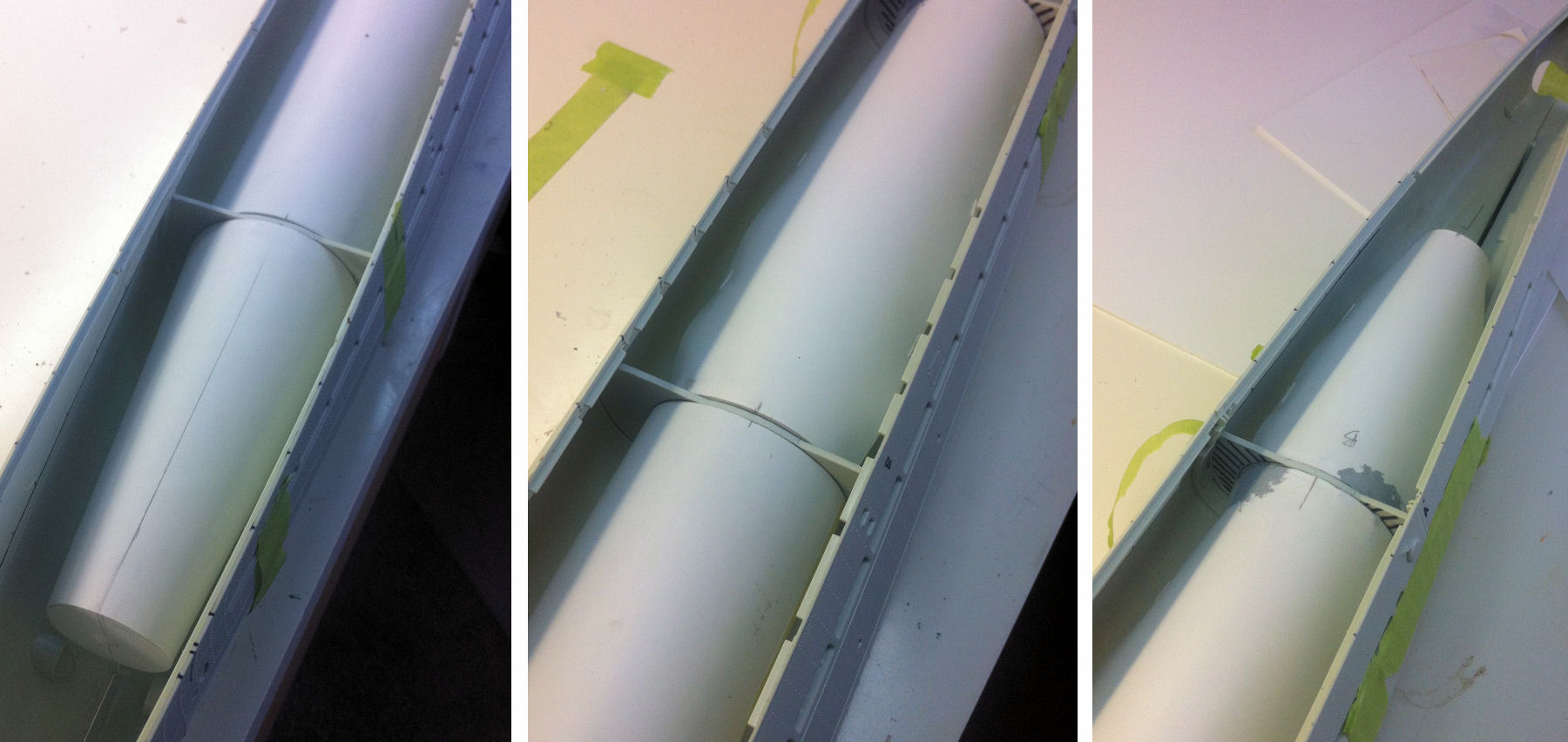
- After the adhesive had set, remove the skin from the lower half of the acrylic tube (since the skin is only needed along the top curve).
- Trim the styrene skin so it is flush with the ends of the acrylic tube.
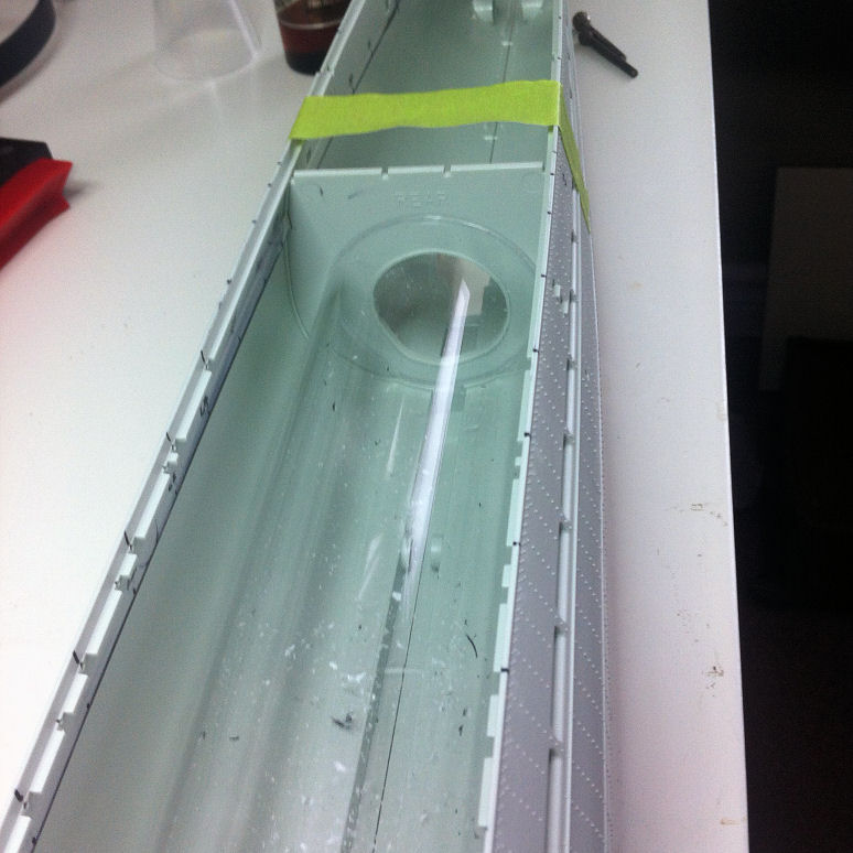
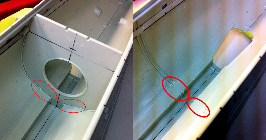
To make the acrylic tube sit properly in the hull, I sanded away the C-bulkhead locating ridges at the bottom of the hull (where indicated in the last picture, below).
Download instructions HERE for making B-C section (fits both Type IXC/40 and IXC)
Pressure Hull : Bow section
Download instructions HERE for making Bow section (fits both Type IXC/40 and IXC)
NOTE:
The forward bulkhead used for the bow section of the pressure hull is NOT included in the U-190 kit; it comes directly from the U-505 kit.
When I continue my U-505 build, I will need to replace that bulkhead.
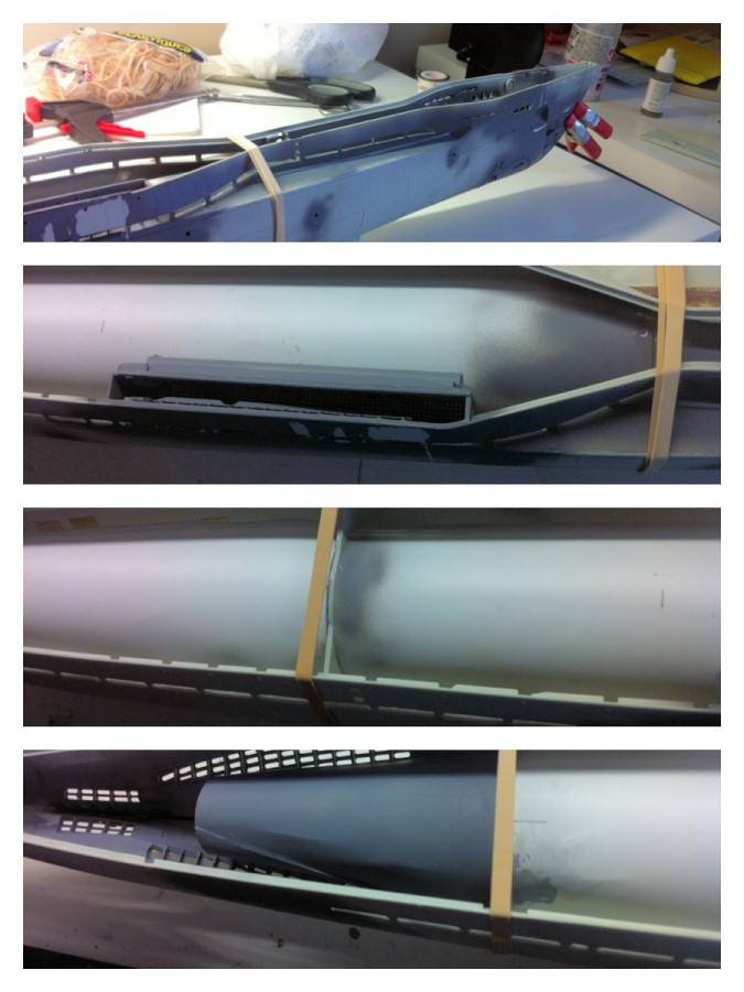
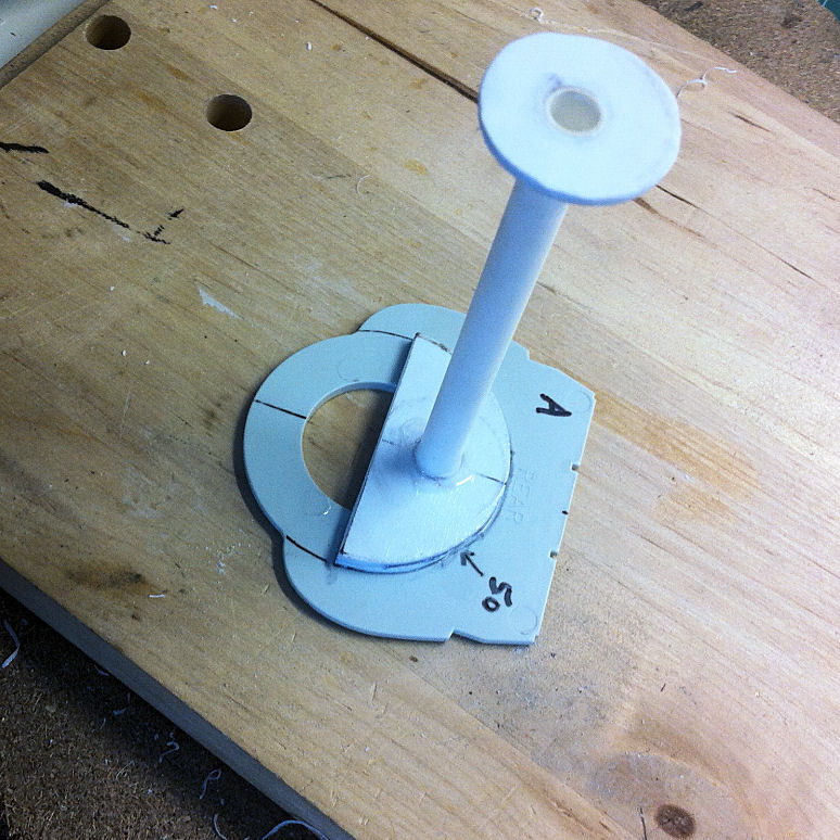
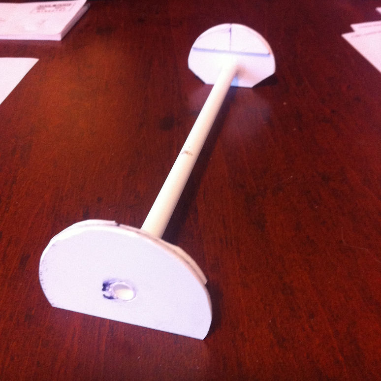
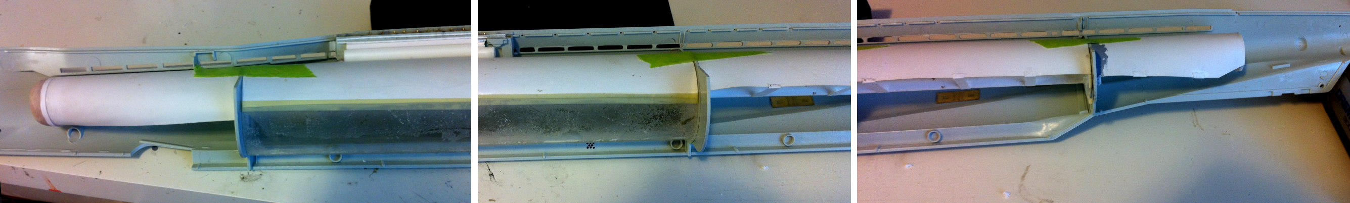
Building the Pressure Hull Sections
Here are some progress pictures of some sections during construction, and in place inside the hull.
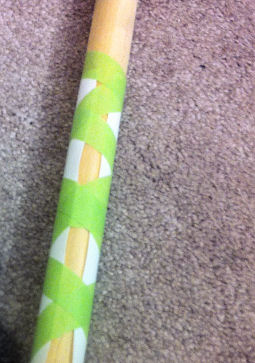
When creating sections of the pressure hull, the thin styrene "skin" would hold a better curve if it was pre-formed around a wooden stick. After that, it would have a more natural curve and would be easier to install around the end pieces.
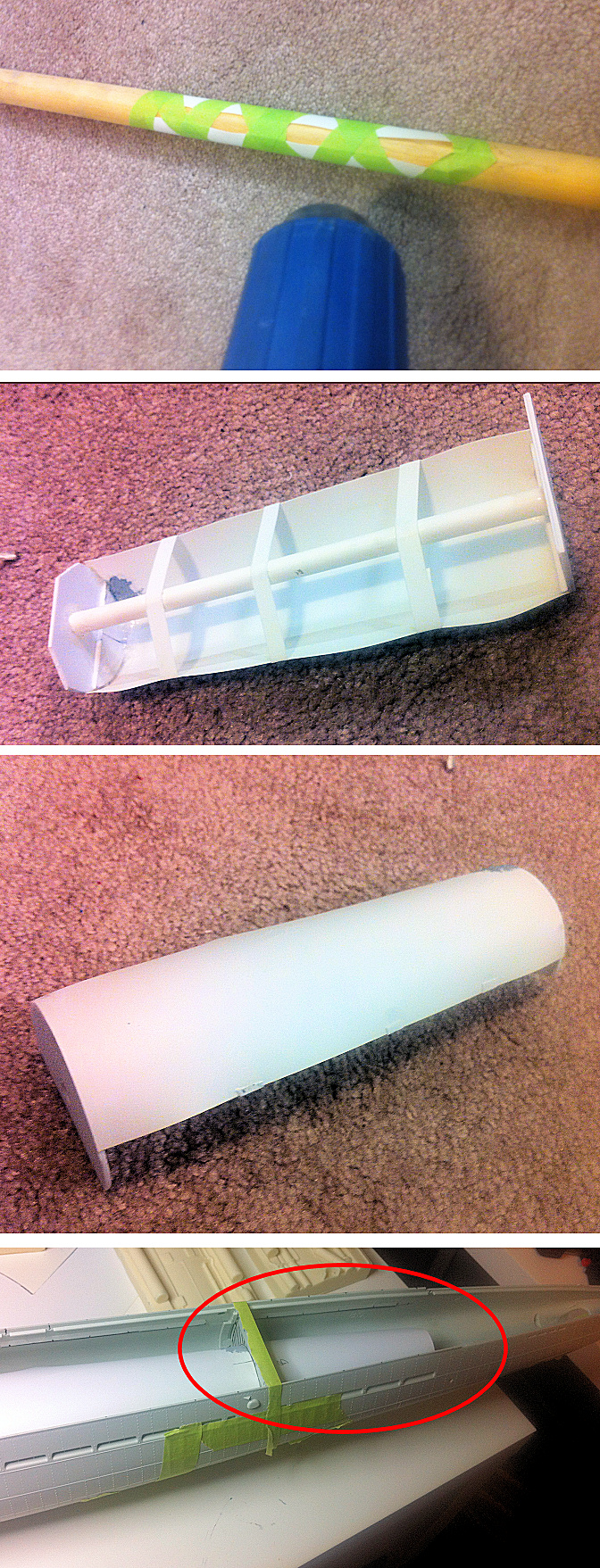

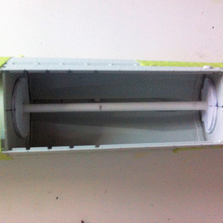
During placement inside the hull, effort was taken to ensure the tops of separate sections align vertically (on either side of the kit bulkheads) to ensure continuity in height along the length of the pressure hull.
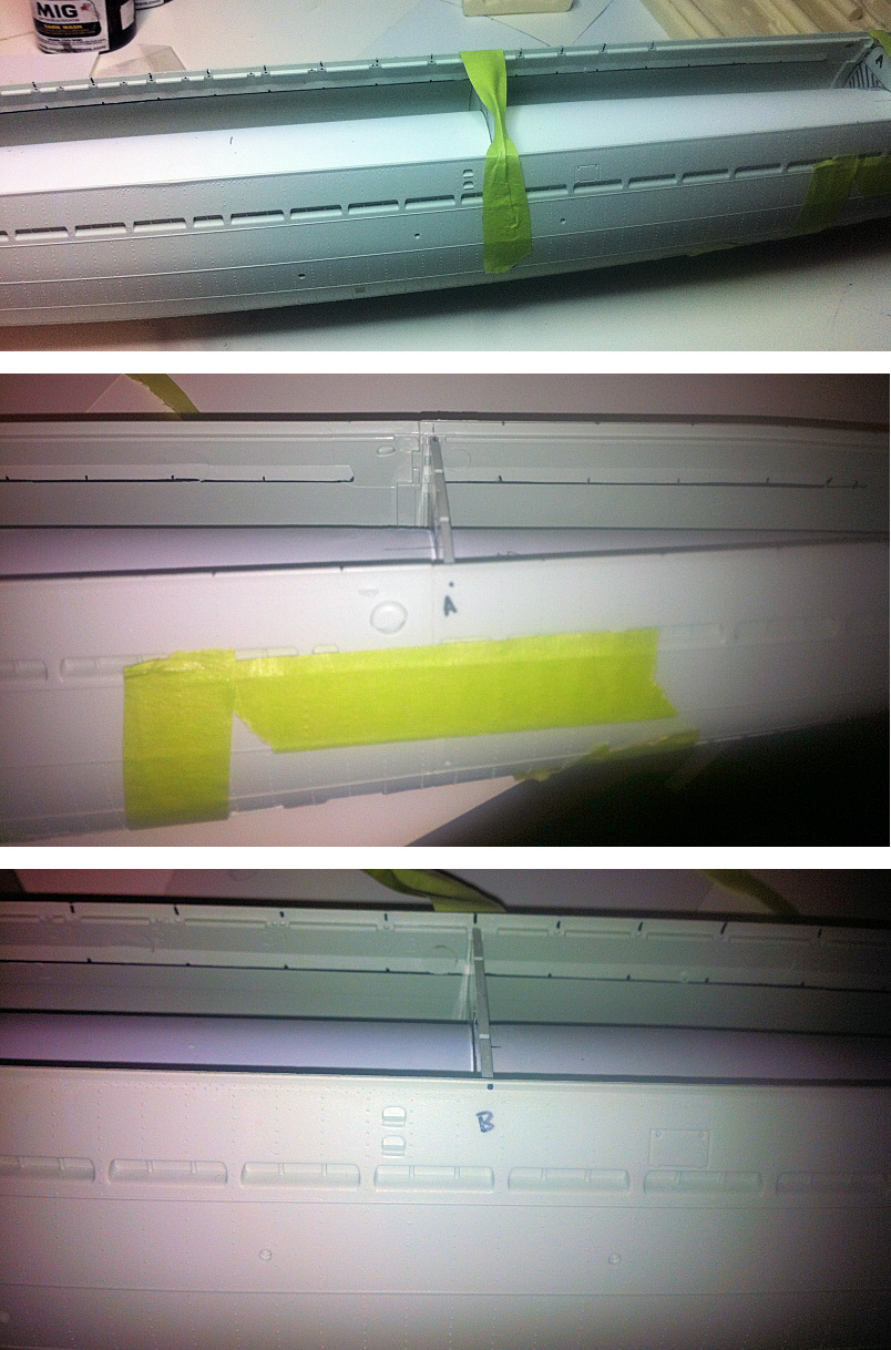
The kit bulkheads were cut down to match the top curves of the pressure hull sections.
This is especially important for the forward bulkhead (from U-505 kit); it would not fit into the U-190 hull without the top being removed.
The forward end of the pressure hull section was created using QuikWood epoxy putty.
Pressure hull mocked up in the IXC/40 hull.
Pressure hull installed.